Buck Boost Regulator Circuit Diagram Schematics Of Buck Conv
Buck boost converter design Buck boost converter dc circuit arduino pwm electronoobs nano schematic homemade circuits voltage regulator potentiometer saved Buck boost converter schematic diagram
Circuit diagram of buck-boost converter Figure 2. Equivalent circuit
Buck boost converter circuit diagram Simple buck converter circuit Buck boost converter bidirectional mosfet sic powerelectronicsnews
Buck boost circuit diagram
Types of smpsSolved the buck-boost regulator shown in fig. 2 has an input 5v buck converter circuit diagramDc to dc buck-boost converter – malabdali.
What is buck converter? operating principle and waveform representationBuck regulator circuit diagram voltage operation waveform inductor peak output theory modes capacitor switch waveforms ripple when off average current Buck 5v regulator circuit using diagram electronic diagramsBuck boost converter circuit diagram.

Buck boost converter circuit diagram
Buck synchronous overcurrent protection regulators converter peak block diagram figure ocp cmcBuck-boost current regulator Synchronous buck regulators and overcurrent protection (ocp)Buck boost converter circuit diagram pdf.
5v buck regulator using lm2678Circuit diagram of buck-boost converter figure 2. equivalent circuit Buck boost regulator circuit diagramBuck regulator peak to peak ripple voltage of capacitor in power.

Buck boost circuit diagram regulator operation modes waveform theory waveforms
Power supply design notes: let's build a bidirectional buck-boostBuck switching regulator smps converter using representation flyback Dc to buck boost converter circuit design wiring view and schematicsBuck boost regulator circuit diagram.
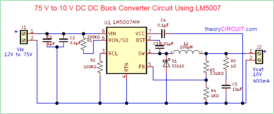
75v to 10v dc dc buck converter circuitBuck converter circuit 10v 75v bom Buck converter equivalentPin on electronic circuits.

Buck boost circuit diagram
Buck regulator circuit diagram, waveform, modes of operation & theoryThe buck-boost regulator in switch mode power converters at engineering Schematic of buck boost converterBuck regulator circuit diagram voltage operation waveform inductor capacitor output peak ripple waveforms switch when modes theory average current derivation.
Circuit diagram of buck-boost converter.Converter buck tl494 circuits dc inverting Buck boost switch regulator figure e2e ti blogs synchronous solution four immunity automotive conducted benefitsBuck converter circuit design.

Schematics of buck converter
Buck boost converter circuit diagram matlabBuck-boost converter circuit diagram Buck boost regulator circuit diagram, waveform, modes of operation.
.


